
The CTOUCH Wallom3 mobile lift system is a solution for the use of large screens in different indoor locations. The lift function ensures that the viewing height is adjusted to the user. The lift should be used for a maximum of 1 min. at a time, followed by 19 min. rest, regardless of the load. Ignoring these instructions will dramatically reduce the system’s lifecycle.
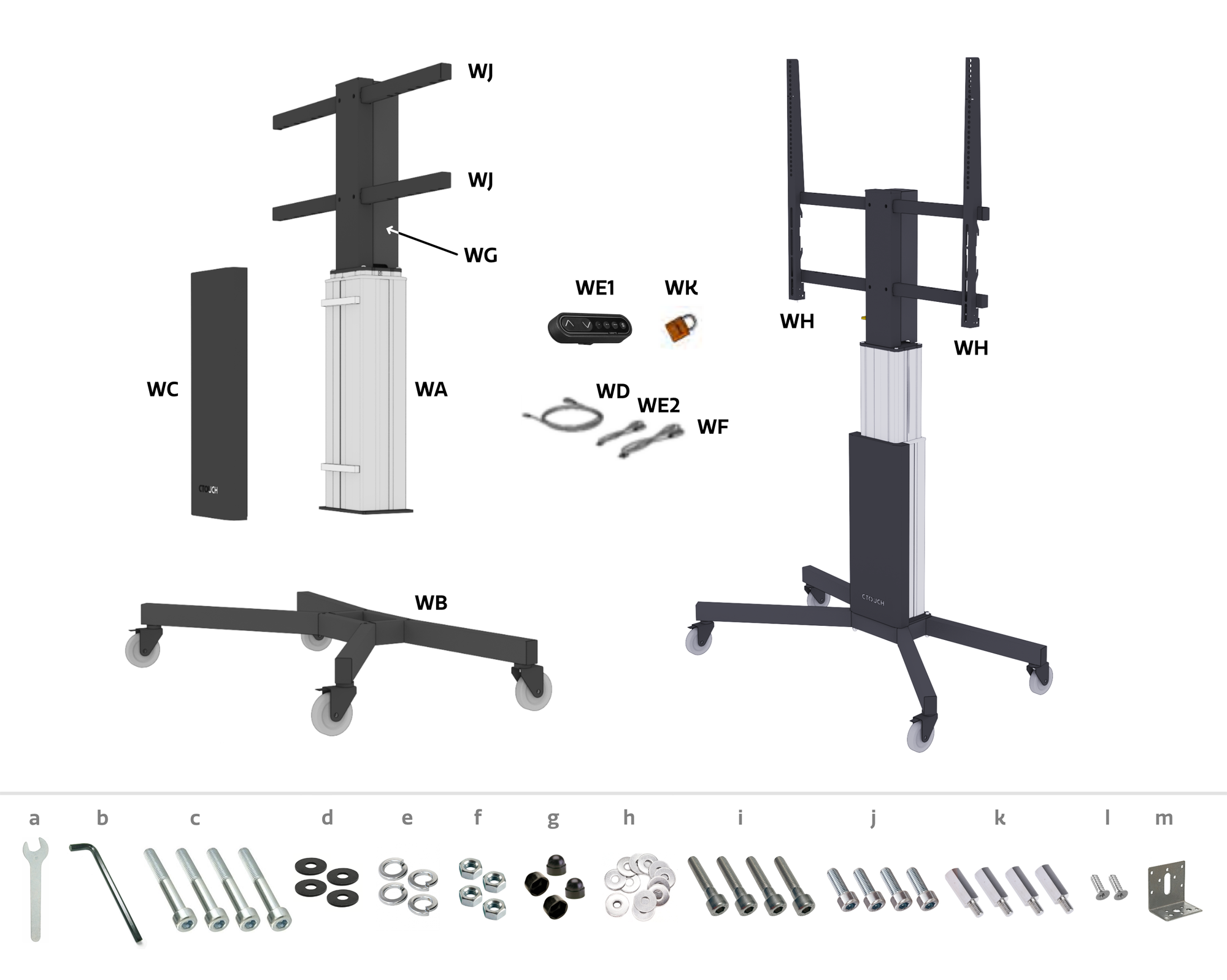
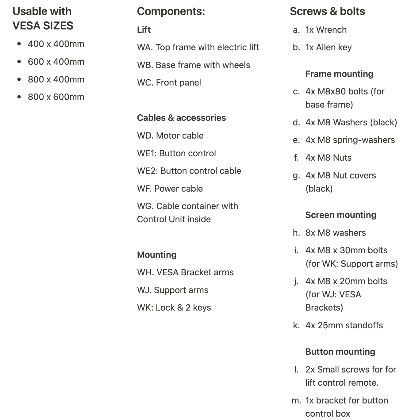
1. Mount the base frame (WB) on the top frame (WA)
Keep the longest arms of the base frame (WB) at the front of the lift's top frame (WA) during assembly. The front of the top frame (WA) has bolt holes near the top.
When installing, position the upper frame (WA) horizontally on its own packaging material (see figure below) to prevent damage whilst aligning the holes.
Bolt the base (WB) onto the top frame (WA) by threading 4x M8x80mm bolts (c) with M8 washers (black) (d) through the bottom of the base (WB), and fastening them with 4x M8 spring-washers (e), and 4x M8 Nuts (f). Ensure the bolts are fastened securely. Lastly, cover the bolts on the top with the M8 Black nut covers(g).
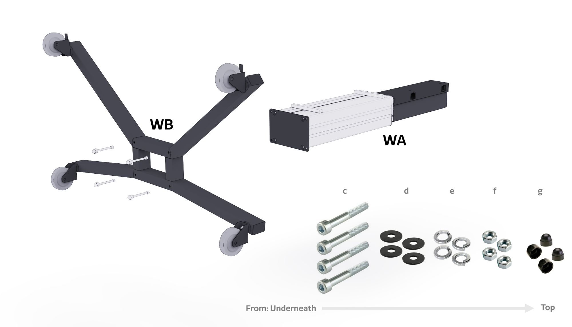
2. Attach the front plate (WC)
Wipe the front of the lift thoroughly with a sanitary wipe to remove any oils. Set the system upright and fasten the front plate (WC) to the lift column (WB) using the tape of the Velcro strips inside the front plate (WC).
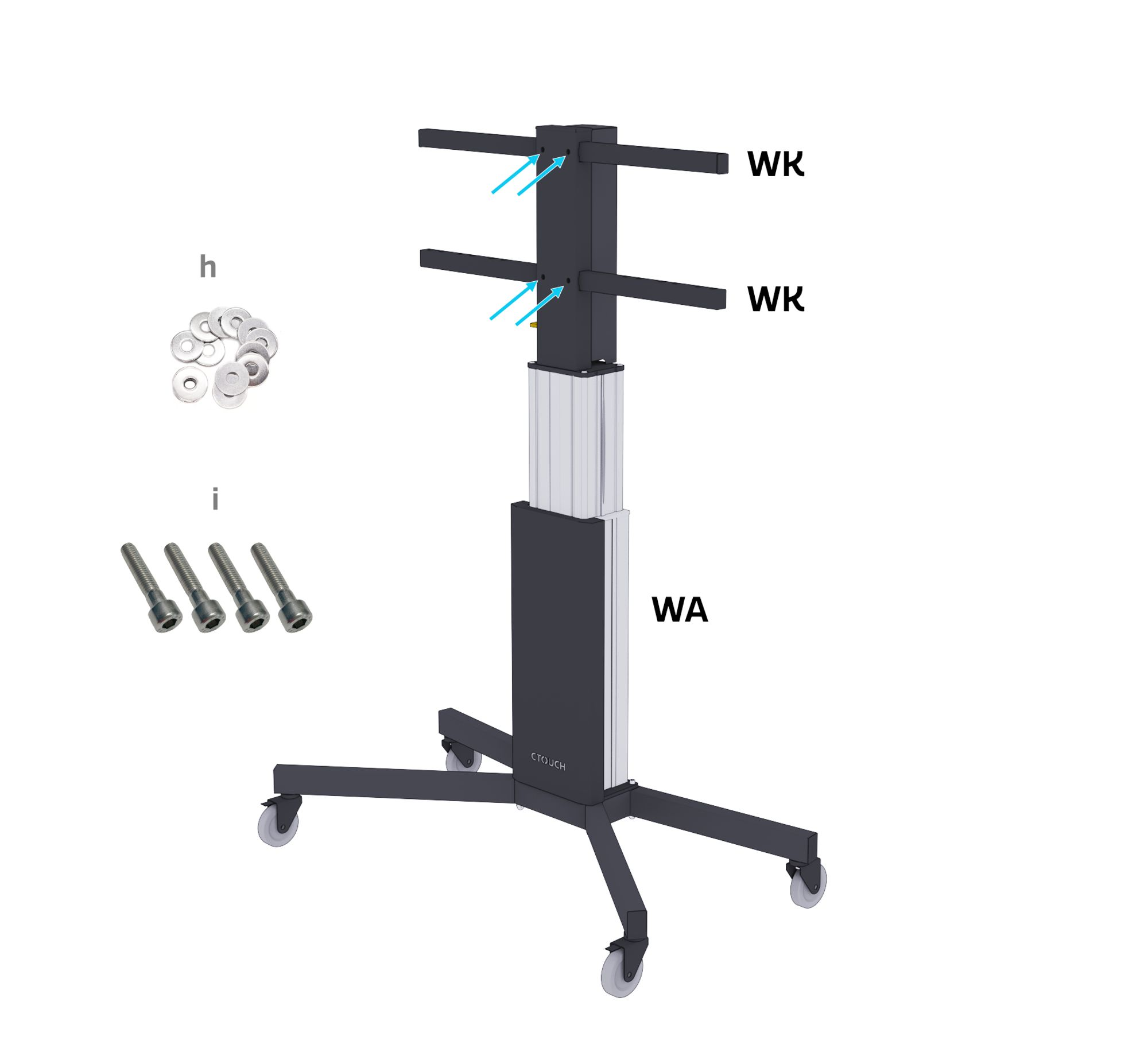
3. Install the supporting arms
Slide the support arms (WK) through the upper frame (WA) and secure with 4x M8 Washers (h) and 4x M8x30mm nuts (i).
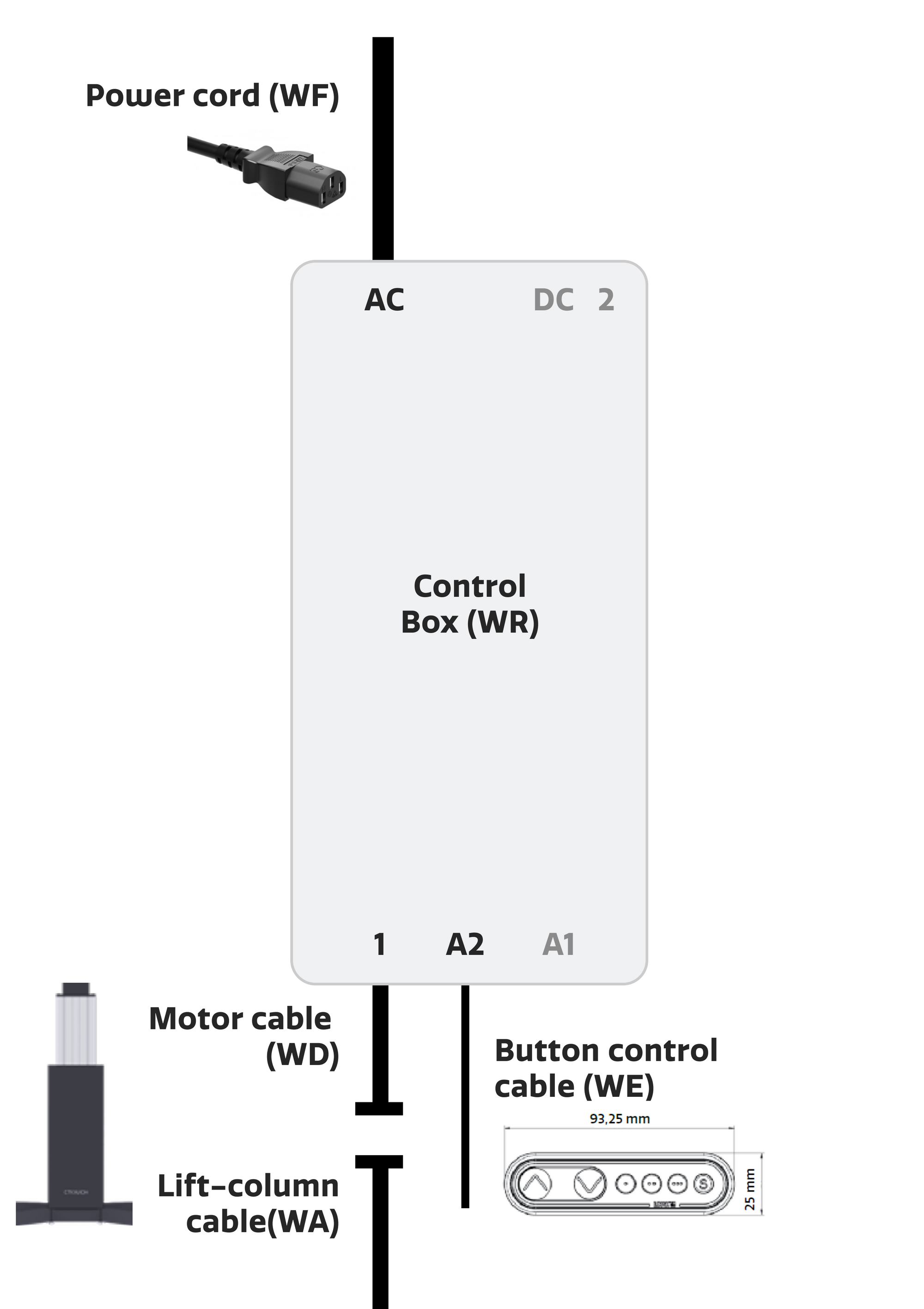
4. Install all cables WD, WE2, and WF
The black control unit is attached to the inside of the cable cabinet (WH).
-
Connect the lift column cable (WA) to the motor cable (WD). Connect the other end to input "1" on the black control unit.
-
Connect the button control cable (WE2) to input "A2" on the black control unit.
-
Connect the power cord (WF) to the "AC" input on the Black Control Unit.
-
Connect the power cord (WF) to a wall outlet. The required voltage is 230 V AC, 50 Hz.
Slide the four hooks of the cable container (WH) into the holes of the plate where the control unit is mounted. Lower the cable container. If the cable container is correctly attached, the control unit and cables are safely covered.
For first use, press the lift button to lower the lift all the way down. From the lowest position the lift can be adjusted to any height. If the panel is mounted horizontally, the button with the arrow pointing to the right is the down button.
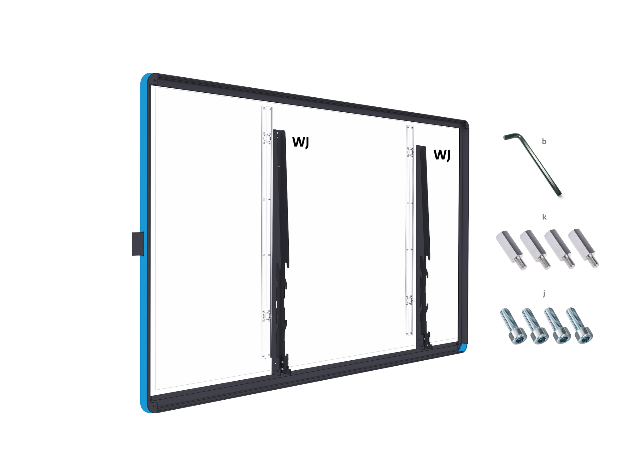
5. Mount the two brackets (WJ) on the back of the monitor
Screw the 4x 25mm standoffs (k) into the VESA screw-holes of the display at the desired height. Then use the 4x M8x20mm VESA bolts (j) to mount the brackets (WJ) onto the 4x 25mm standoffs (g) and then into the VESA screw-holes of the display at the desired height. This should add a distance of 25mm between the brackets (WH) and the display. Ensure that the brackets are mounted at the same height on the display. Securely tighten all VESA bolts (e) using the Allen Key (b).
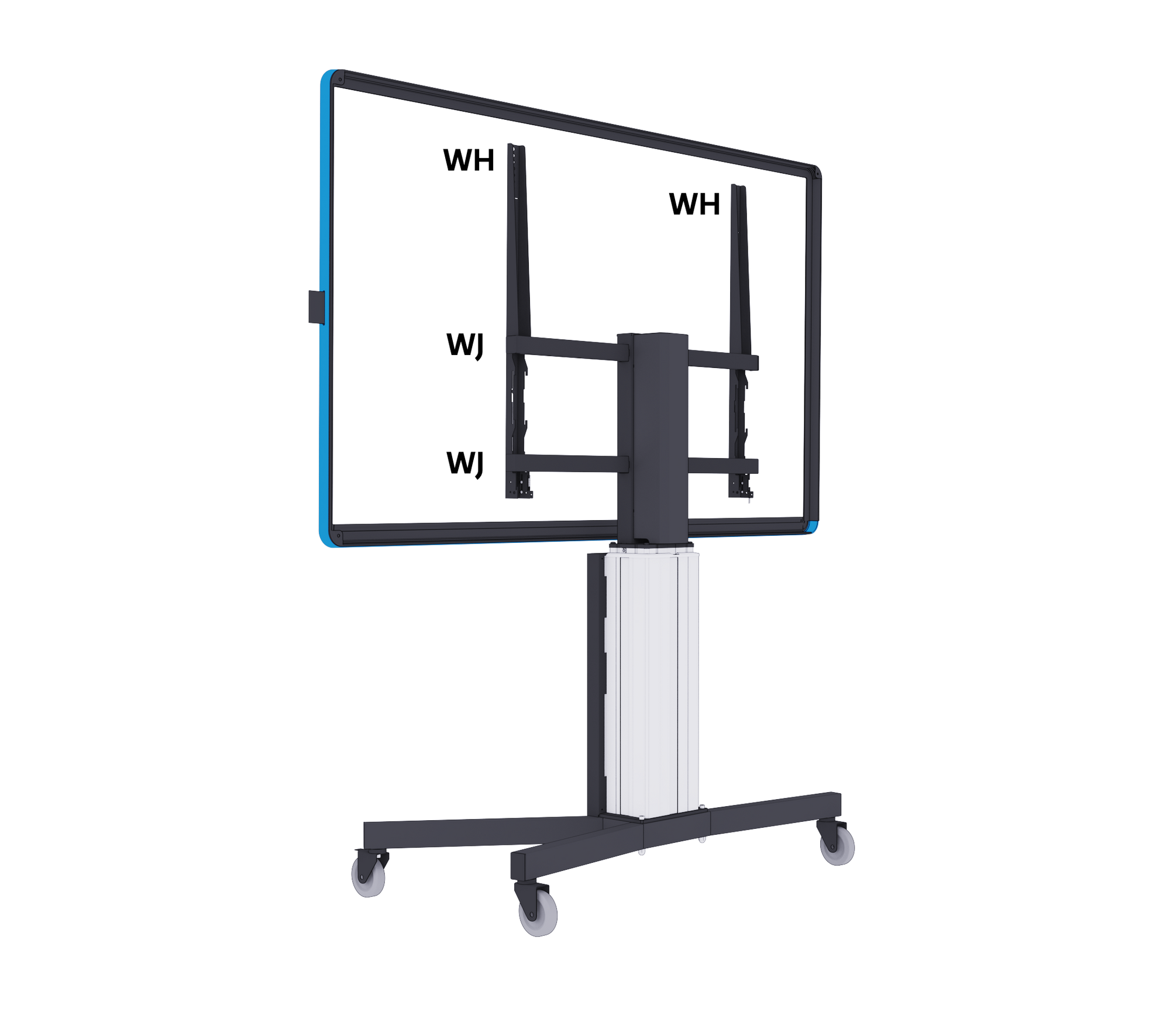
6. Suspending the monitor
Important: Put the brakes on the wheels before suspending the monitor.
Hang the monitor on the highest support arm (WJ) first at a slight angle, and then straighten it to vertical until the hooks on the VESA brackets (WH) connect completely with both support arms (WJ).
In their lowest positions, the estimated lowest height of the display from the floor is noted below. Be aware that the brackets (WH) could be seen above the top of the display in their lowest position in some situations:
|
Lowest point |
55 inch |
65 inch |
75 inch |
86 inch |
|---|---|---|---|---|
|
Canvas |
852mm |
822mm |
819mm |
830mm |
|
Canvas (using 25mm standoffs) |
852mm |
732mm |
729mm |
679mm |
|
Neo |
- |
- |
728mm |
742mm |
|
Riva |
853mm |
822mm |
819mm |
815mm |
|
Riva (using 25mm standoffs) |
853mm |
732mm |
729mm |
680mm |
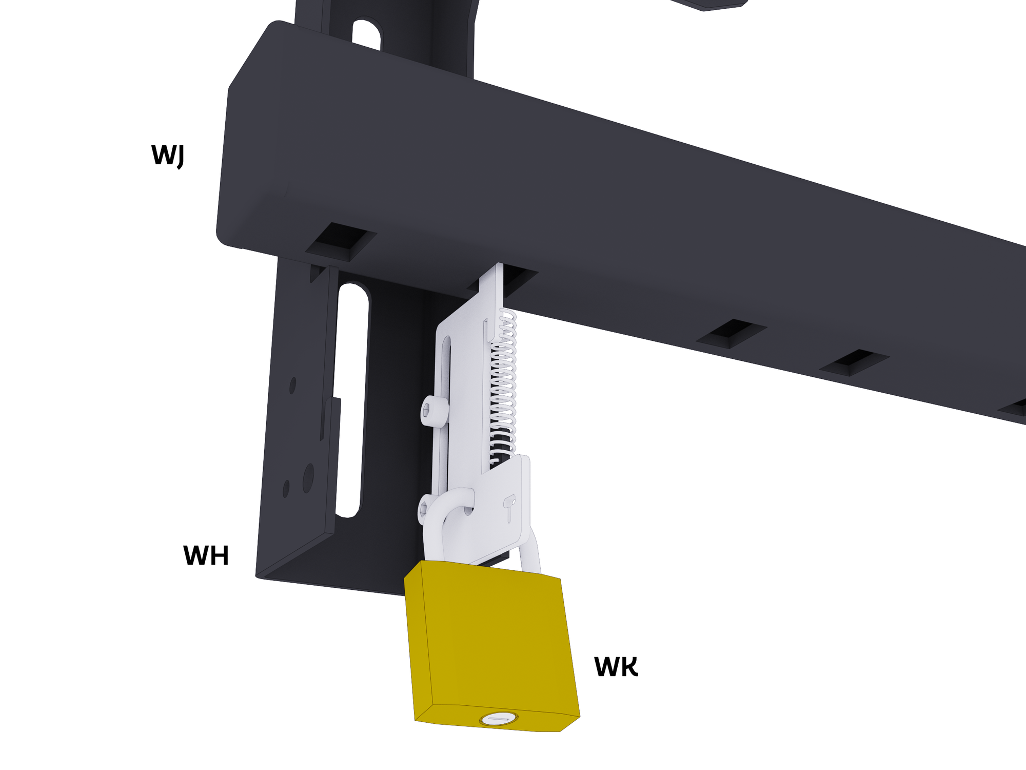
7. Important! Slide the securing plate completely upwards
Slide the security plate of brackets (WJ) completely upwards. Preferably, hang a lock (WK) through the 2 holes to ensure that the screen cannot come loose.
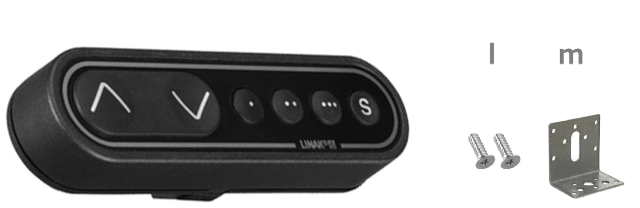
8. Install the button control panel
Install the button control (WE1) on the edge of the screen with 2 screws (l) and the bracket (m).
Changes or modifications will void all warranties and exclude any liability. This user manual contains detailed instructions about your product. Pictures and illustrations in this manual are for reference only and may differ from the reality. Design and specifications are subject to change without notice.